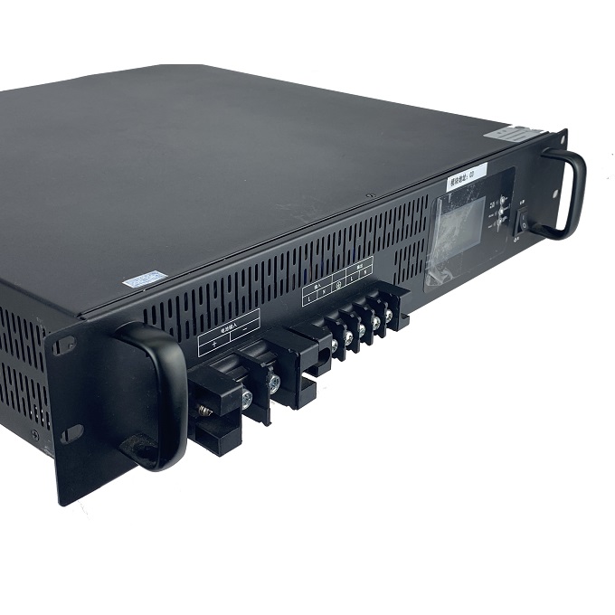
Talking about the protection scheme of pure sine wave 220v inverter failure
Communication high-frequency inverters need to achieve long-term uninterrupted power supply to key loads, which places extremely high requirements on the reliability of high-frequency inverters. In the actual application environment, the user may cause the inverter output short circuit due to operating errors or environmental factors, or the inverter bridge arms may pass through. At this time, the inverter power tube will have a large current passing (this article mainly focuses on IGBT explanation can also be applied to MOSFET by analogy).If such fault currents are not detected and effective protection actions are implemented, the collector or drain current of the IGBT will far exceed the safe working area, and the IGBT will cause high transient currents. Power loss burns, and there may also be overvoltage breakdown damage caused by overcurrent.
Output short-circuit protection: the inverter needs to be able to withstand the short-circuit impulse current repeatedly, and the inverter can be turned off after maintaining 200ms. This requires the current flowing through the IGBT during the short-circuit to be controlled at ICRM (repetitive peak current, generally ICRM=2 IC nom).

Bridge arm through protection: For example, VT2 itself fails and is short-circuited by external electrical connections. When VT1 is turned on, the bus is directly short-circuited through VT1. This through current rises very fast, generally within 10 μs that can rise to the IGBT rated current After the bridge arm through-through occurs, it is necessary to quickly detect this fault, block and deadlock the IGBT drive, and allow the drive signal to be turned on again until the system command is reset. In the total life cycle, the general IGBT can not withstand this type of through current more than 100 times. This type of shoot-through protection needs to turn off the drive before the IGBT current does not exceed ISC (transient peak current, generally ISC=4 IC nom) and turn off the inverter at the same time within 10μs.
1 Output short circuit protection
Install a HALL current sensor at the label 4 to detect the Lf inductor current. When an output short circuit occurs, if VT1 is turned on, the voltage UC1 short-circuits through VT1 and the inductor Lf, and the inductor current rises rapidly. When the current reaches a certain range (greater than the normal operating current) , Less than the repetitive peak current ICRM), the VT1 and VT2 drives are blocked. At this time, the inductor current ILf begins to decrease. When the current drops to a certain level, the drive blockade signal is cancelled. If the output has been short-circuited during this process, when the next drive comes, the inductor current starts to rise again. When the short-circuit protection point is reached, the IGBT drive is blocked again. After 200ms of repeating this, the software logic can judge that the output short-circuit has occurred at this time. Turn off the inverter.
2 Overcurrent protection of bridge arm through
First of all, in order to avoid the through failure caused by the driving signal of the upper tube VT1 and the lower tube VT2 at the same time, it is necessary to consider adding a dead zone in the driver software, and on the other hand, it is also necessary to adjust the upper and lower tubes on the hardware circuit. The drive waveforms of the two are interlocked by hardware. When the drive levels of the upper and lower tubes are at the same time, the drive voltage is automatically blocked.
In addition, the IGBT may also instantaneous breakdown due to overvoltage, or its own avalanche failure short-circuit, or short-circuit caused by electrical connections caused by external reasons. Protection measures can not completely avoid the possibility of bridge arm shoot-through in the converter, so how to detect the shoot-through fault in time when the bridge arm shoot-through occurs and protect the IGBT to avoid IGBT burning is particularly important.

